Saturday, October 9, 2010

Steering gear

Steering gear is a component of the steering system that allows you to straighten the front wheels and also to increase the moment of the steering wheel, so that the steering becomes lighter. Steering gear consists of a gear or teeth that are useful as gear reduction so that the moment of driving the increase.
Teeth in the steering gear ratio is between 18 to 20:1 means 18 turns the steering wheel the same lap times will result in a Pitman arm. But for the ratio of 20:1 means the steering wheel is 20 rounds will produce 1 time round Pitman arm.
Surely you are confused what is a Pitman arm ..? I will first explain the construction of the steering gear, so you know what the Pitman arm.

Before I explain the construction is a good idea to first know the various steering gear is:

* Recirculating ball type (this type used on a large haulage vehicles)


* Rack and pinion type (this type used on vehicles with a light haulage)


How to calculate the ratio of the steering for both types of the above is:
* For the recirculating ball type formula is: number of steering wheel rotation equals the number of Pitman arm movement.

* To Rack and pinion type formula is: number of rounds equal to the amount of steering wheel turns the front wheel angle.

Torque convertor


Torque convertor is a hydraulic clutch that is in use on the automatic clutch. on a car that uses automatic machine, certainly do not have a clutch lever. but that does not mean a car that uses automatic transmission does not use the clutch. many people consider that automatic cars are not using the clutch, but in fact they are wrong.

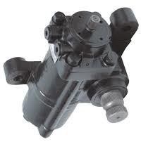
From the picture above, you can see that the construction of Torque convertor very simple.
Components of the Torque convertor consists of PUM impeller, stator and, Turbine Runner.

* Pump impeller is a component associated with the oil pump in automatic transmission, pump impeller with welded joints permanently fastened to the flywheel.

* The stator is a component that allows you to double its oil power in the Torque convertor for the machine does not become dead weight and play at the start of transmission.

* Turbine Runner is a component related to the transmission input shaft.

In this convertor Torque in which there is oil or oil as the fluid rotation of the flywheel successor to the transmission.

* How it Works Torque Convertor:

When the round is still slow runner turbiner:

At the time the new machine live the first time that rotates on convertor torque is the component impeller pump. Pump impeller are permanently connected to the flywheel using welded joints. While living at the time the new engine turbine runner is still in a stationary position. When the pump impeller rotates, the oil in the torque convertor will be stirred. This will make turbiner runners become involved spinning slowly - land. But the rotation of the turbine runner is still slow. This will make the pump impeller get a load, if this is allowed then the engine will die. Because the rotation of the pump impeller suspended, automatically turns the flywheel will be captured as well that can make the machine becomes slow and eventually die. That is why the torque convertor paired stator, where the stator there are bearings that work in one direction. That these bearings can only rotate in one direction only, whereas in the opposite direction of this bearing will not rotate. Use of this stator is turned toward the return flow of oil from the turbine runner to the pump impeller. The direction of this return will make the pump impeller will increase strength, because the direction of return oil is directed to encourage the pump impeller. So at this stator does not rotate.
This also occurs when the position moved to the position of the transmission lever into gear.

When the runner is fast lap turbiner:

When the runner is fast lap turbiner alias the same as rotation pump impeller, the flow of oil from turbiner runner will not be deflected more. The flow of lubricating oil is going straight. And pump impeller, stator and turbiner runner rotates in the same rotation speed.

Sunday, October 3, 2010

How it works and the construction of the coil ingnition

Ignition coil or in the Indonesian language interpreted by the ignition coil is a component of the ignition system that allows you to raise the voltage of the battery is 12 volts into high voltage 10 KVolt or more. Ignition Coil in a critical size that occurs in the spark plug ignition.

By construction ingnition coil comprising:
1. Cable Positive: Part of the coil are connected with cables that have a positive electrical current, to the circuit in the positive cable cars connected by cables to the fuse.
2. Negative cable: Part of the coil connected by wires to the distributor (for the ignition system on the car)
3. Secondary coil: coil which form part of the cable winding number of coil windings more than the primary.
4. Primary coil is: which form part of the coil winding wire windings that amount less than the secondary coil.
5. Secondary is part of the coil which is connected with high voltage wires to the distributor (for cars). As for the secondary motorcycle big black cables are connected directly to the spark plugs.
How it works coil which I discussed here are the series of ignition system on the car using the platinum:
1. When electric current flows into the positive, then the primary winding will be electrified. This will cause the magnetism in the primary winding. An electric current will flow from the primary winding to the negative terminal.
2. At platinum open, then the relationship between the negative terminal to the masses will be disconnected. Areus power of positive current will not flow into the primary winding. This will lead to magnetism at primary lillitan be lost. With the loss of magnetism at the primary winding, then arises the induction of the secondary winding. Where the secondary winding will generate electricity with very high voltage. Electricity generated at the secondary winding will be channeled to the secondary terminal to be forwarded to the high voltage cable.
For ignition with CDI, coil workings remain the same. That in principle the cause of induction of secondary windings, resulting in power at the secondary winding with a very high voltage.

Steering Column


The theme of this lesson is an explanation of the steering column. Steering column is one component of the steering system on the car. Steering column is part of the steering system that connects the steering wheel to the steering gear box. Steering column consists of the main shaft, the shaft driving the wheel of the forward motion of the steering wheel to the steering gear box. So actually the steering column is a pipe sleeve that holds the steering shaft play in driving forward motion.
On car steering column is paired with the bracket and fastened to the body of the car. Installation and manufacture of steering column is to be regarded with care, because the steering column must be designed to absorb the thrust into the steering wheel, when the collision occurred. So in the design of steering column is to be regarded with care - really for the safety of the driver when the collision occurred. In one particular car type steering column is designed, can come down when the collision occurred, so that the safety of the driver can be maintained.
In addition to the driver's attention to safety factors, there are few cars that make the vehicle or its steering column can be set in accordance with the right driving position. On Tilt type steering, the driver can adjust the steering wheel in a vertical, by shifting the steering wheel in a vertical position. While on type Telescopic steering, the driver can set long-and short steeriung column, so the driver can keep or hold the steering wheel position.

Transmission Mods

Modification of transmission is often known to alter or add to its gear ratio. Once you know how to calculate gear ratio, then you can make changes by changing the gear ratio. But not only that to develop and modify transmissions, there are a few tips that I will give to you in modifying transmission. Let me just on the tips that I will give as well as explanations:

1. Changing the gear ratio
This is often done by adding the ability modifiers in either vehicle motorcycle or car. If the ratio of gear teeth into - 4 of your vehicle is 1, then you can turn them into higher, eg 0.9 or 0.8, and so on. But I remind you, the excessive increase of gear ratio will make your vehicle's engine becomes exhausted alias lackluster. To simplify my explanation, then I suppose that with a mountain bike with a lot of teeth - teeth that can be moved - moved. I'm sure you all must have seen and may never have a mountain bike. If we want to start pedaling a mountain bike, then we will use a large gear ratio. The point is to make the composition of the front teeth using a small gear, while the rear teeth using a big gear. Certainly the composition of teeth will make you a light in pedaling a bicycle, but bicycles can not be sped by quickly. After the bike is running, you certainly will increase your bike speed by changing the composition of teeth, that is changing the front teeth with teeth larger. Your bike will go faster than ever before. Then you also will increase the speed again, by changing his front teeth became larger, and your bike will go much faster again, so onward. But there are times where the tooth arrangement which continues to be enlarged on his front teeth, you have exhausted or sluggish, and eventually you lose to a big gear arrangement in accordance with the ability of your energy. Similarly, the engine, just like you. The machine has a maximum power capability that remains constant alias, so if the change gear ratio gearnya too excessive, the engine can be sluggish.

2. Enlarging the diameter of gear transmission
You certainly still remember the parable of the lever at the time in school physics lessons first. For objects can be easily lifted, then lever the lever must be made longer. Similarly, the change in the diameter of the transmission gear will make personnel changes, such as for example the lever lever. Greater diameter, the same as a long lever lever. Meanwhile, the smaller the diameter, the same as the short lever lever. The conclusion by creating a larger gear diameter, will make the engine into a lighter in a vehicle wheel. And usually a vehicle that uses a larger gear transmission will make certain teeth into a long breath. For example on one tooth that has a large diameter, it can reach speeds of 50 km / h, while the teeth are small diameter only reached 20 km / hr. But you need to consider also changes in the diameter of this gear will make the arrangement of gear transmission becomes greater. For that into account also the place or the home of such transmission.

Torque Convertor

Torque convertor is a hydraulic clutch that is used on automatic transmission. In a car that uses matic transmission, certainly has no clutch pedal. But that does not mean a car that uses matic transmission does not use the clutch. Many of the community generally considers that the car does not wear matic clutch, but in fact they are wrong, because it really does not use the clutch pedal, but still use the clutch. And now I will explain the construction of the torque convertor.

Construction convertor torque:
From the picture above, you can see that the construction of the torque convertor very simple. Components - convertor torque component consists of pump impeller, stator and turbiner runner.
• Pump impeller is a component associated with the oil pump on matic transmission. Pump impeller with welded joints permanently fastened to the flywheel or the flywheel.
• The stator is a component that allows you to double its oil power in the torque convertor, so the machine does not become dead weight and play at the beginning of transmission.
• Turbine Runner is a component associated with the transmission input shaft.
In this convertor torque in it there is oil or oil as the fluid rotation of the flywheel successor to the transmission.

Saturday, October 2, 2010

Construction Manual Transmission

Today in particular I will explain specifically about the construction of a manual transmission to vehicles, especially cars, to motorcycles in fact almost the same, there is little difference only. Before starting this discussion, you should first recognize the power transfer systems or power train, making it easier for you in understanding this material. In the car we know there are some power transfer system, namely FF, FR, RR and 4 WD. Each type uses a different transmission. For the FR vehicle (front engine, rear drive) using the transmission, while for type FR, RR and 4WD use transaxlePastinya to who are beginners in learning the transmission, confused by the second term above. I will immediately explain just about the construction of transmission and transaxle.

Transmission Construction
1. Clutch housing is a cover for the components - clutch components are mounted on the flywheel or the flywheel. In the clutch housing is also mounted components - components that drive the clutch fork (which is useful to suppress relaease bearing). Clutch housing front section attached to the machine using the connection bolts.
2. Transmission case is the house where the installation of the output shaft, counter shaft gear and the tooth - teeth other transmissions. Transmission case is filled with useful transmission oil to lubricate the rotating gear transmission and other transmission components such as bearings, etc..
3. Counter shaft and counter gear is a transmission gear arrangement which rotates to produce the ratio of teeth with a tooth - teeth the other transmission.
4. The output shaft is the transmission component that allows you to continue the rotation transmission ratio to the propeller shaft.
5. Input transmission shaft is a component that receives the round of coupling and k meneruskannay teeth - tooth transmission to change the speed and torque.
6. Gear shift is mechanisme transmission component that allows you to manage relationships tooth - teeth in the transmission that works on every level of a certain acceleration. Mechanisme Gear shift is driven by the driver via the gear lever.
7. Extension housing is a component of the transmission output shaft cover or shield from dust or dirt. Or more simply we refer to as the back cover of the transmission.
Construction transaxle
You can see that as a general construction is the same transaxle transmission, but the transaxle, there is one additional component of the differential assembly. Semuan other components are the same transaxle transmission.

Knowing in detail Radiator

Now I will explain the construction and function of the radiator is used in cooling systems. As you may know that the radiator is a place to accommodate the cooling fluid used to cool the engine. This fluid is different - there are kinds of uses special liquid cooling, but some are using water only.

The construction consists of the radiator tank top, the middle tank and the tank bottom. On tank top is a hose pipe connected to that channel water from the engine coolant. While in the middle tank terdapar cooling pipe rolling and fin are made useful to reduce the heat from the engine cooling water. This cooling water will flow on to lower radiator tank. . At the bottom of this tank there is pipe the output to be connected with hoses to the water pump. In short the flow of cooling water in the radiator is as follows: Water cooling of the engine will go through a pipe on the tank top and then fill the tank top. This cooling water will flow into the cooling pipe at the tank center to reduced temperature. Then it will enter the cooling water into the tank bottom, then sucked out of the tank bottom due to water pump (coolant pump) work.

How to calculate gear ratio transmission

Gear ratio or gear ratio is a number that indicates the level of the small size of the teeth on the transmission. This gear ratio will determine the acceleration resulting from the combination of teeth - the teeth in the transmission, on each - each level of acceleration. In a motorcycle transmission generally uses a combination of two gear to produce a level of acceleration. While the cars generally use a combination of four or more teeth to produce a level of acceleration. Suppose the speed of gear 1, the change in acceleration of the clutch to the transmission output shaft using a combination of 4 teeth (for cars). Teeth - tooth eye tooth has a different number on each - each tooth. The number of teeth of different eyes - the difference is what will make a difference in the rotation and power transmission.

Now I will just discuss how to calculate gear ratio:
1. combination of 2 teeth
For a combination of two teeth we use the formula:
gear ratio = B: A

2. combination of 4 teeth
For the combination of 4 teeth we use the formula:
gear ratio = (B: A) x (D: C)

3.kombinasi 5 teeth
For a combination of five teeth we use the formula;
gear ratio = (B: A) x (E: C) x (D: E)

Example:
A number of gears is 10, B = 30, C = 20, D = 40

gear ratio = (30: 10) x (40: 20)
= 3 x2
= 6

So gearnya ratio is 6, the point is 6 times round the clutch will generate 1 output turns on the transmission output shaft.

Piston Ring End Gap Between

Piston rings are not made fully connected like a bracelet, but one part is cut. This piece makes a piston ring as a bracelet that is lost on one side. The purpose of this is breaking piston rings for piston rings have a gap for expansion at the moment to conduct heat. This gap will be changed to change depending on the size of the cylinder wall expansion due to heat in the engine. Standard gap which is generally at room temperature is 0.2 to 0.5 mm. As not all piston ring gap is the same, depending on the specifications and characteristics of each - each machine.

At the time of the cylinder block in oversized then the gap between the end of the piston ring which is the basis of measurement. The cylinder will dikorter or in oversized to the size of the gap between the end of the piston ring reaches the size of 0.2 to 0.5 mm. When you do the inspection on the cylinder block, the piston ring gap can be used as the basis of examination and measurement to determine whether the cylinder block in korter necessary or not. If the gap between the end of the piston rings exceeds the standard, then it should dikorter cylinder block and pistons and piston rings must be replaced with a larger size.
Gap between the tip of the excessive piston ring will make the engine compression capability will come down, otherwise if the gap between the end of the piston ring is too small will make a curved piston rings when the heat and make the cylinder walls become damaged. Bending piston ring is due to the hot engine, causing expansion of piston rings. Since the end of the piston rings are too narrow, the space for the expansion piston ring becomes less and result in bent piston rings.

Components - Main Components Brake Disc

Components - The main component consists of a disc brake disc, caliper, and brake pad. Thirdly it is a component - the main component of brake discs used on the car. For this time I will only discuss the type of disc brakes on the car alone. Well I will explain the components - these components one by one.

Disc is a disc brake component that allows you to receive the grit from brake pad during braking done. This disc is connected with car wheels through the bolt connection. So when the car is running and the wheel rotates, the disc also rotates.

Disc brake caliper is the component that allows you to receive the forward braking force of brake fluid to put pressure on the brake pad. On the caliper there is a piston which receives the pressure of brake fluid and will move forward out to push the brake pad. Caliper attached to the chassis of the car and did not move or say anything at the time the wheel spins.

Brake pad is pressing the brake components and contact with the disc. This brake pad attached to the caliper brake and can move back and forth when the piston in the caliper pressing. Brake pad more often referred to as brake.

Friday, October 1, 2010

Muffler Exhaust System

Automobile exhaust is one of the existing components on the car that serves as the conduit for flue gas. Automobile exhaust also affects the performance of the engine, if the position and its construction does not fit the machine's performance will go down as well if we want to maximize the machine work, many asthmatic car made modifications to the waste channel.

In our automobile exhaust installation can not be arbitrary, there is a maximum size of the diameter of the exhaust pipe is allowed. Maximum size is to maintain a balance between the speed of the exhaust gas with the amount of exhaust gas. Too small size means the diameter of the gas velocity decreases dump large amounts only, whereas if too large diameter exhaust, then dump the gas velocity low despite the high number of dump gas.

From the side of the car, the exhaust is very vital role. In addition to regular machine service, service kanlpot also do not forget the goal is done periodically to keep that always exhausts in good condition. Many car users who come to the garage the car to make modifications to the header, the diameter and length of main pipe and the Collector. Because by doing modifiaksi in this section, the torque and power bands will change.

In addition, automobile exhaust also serves to establish the roar of the engine sound, There are two parts of exhaust systems that determine the tone of voice, the resonator and muffler. Do changes in these two parts will change the sound character of our cars without compromising performance (torque and Power Bands.)

Resonator placed behind the collector (headers) or behind the Catalytic Converter (CAT). Resonator working principle is to use this method of wave reflection and which will determine the basic tone of voice. The longer the resonator, the more the waves are reflected / reflected that interact with the wave coming, so the sound becomes small.

There are three types Muffler or silencer to get different voices - different. That is chambered (there is room divider / barrier), Straight-Through, Twin-Pass (Double Tail Pipe).

Generally for the resonator is not equipped with glass wool for combustion exhaust gas in place was still hot (refrigeration not yet complete). So a good cooling is needed, otherwise the gas leakage will occur.

Usually the leakage would occur if the packing of the connection has been burned, although only small but it will affect the performance of our automobile exhaust. Therefore always check the exhaust manifold gaskets. Collector's Connection to the pipe behind it.
Submit Express Inc.Search Engine Optimization